

Groundwork requirements for gates
All our quotations, unless stated, price the groundwork separately. Many practically minded customers chose to carry this out their selves to save cost. We are happy to advise so far as is needed.
Please refer to the guides below for hinging and sliding gates
Groundwork requirements for Hinging Gates
From our factory near Braintree Essex we assemble and test every hinging gate before delivery.
Unique to us, every hinging gate has a crossbar linking the posts together, enabling the gate to be transported and fitted in one piece. This designs out fitting error and allows the electrics to be assembled and fitted in a clean environment out of the rain and mud.
The groundwork requirement consists of 2 800mm deep post holes with a 300mm deep cross trench between them. A second pair of photocell beams are then fitted behind the sweep of the gates and the wire run back to the gate posts.
Mains or solar power need to run to the rh post looking outwards.
Groundwork Requirements For Cantilever Sliding Gate Installations
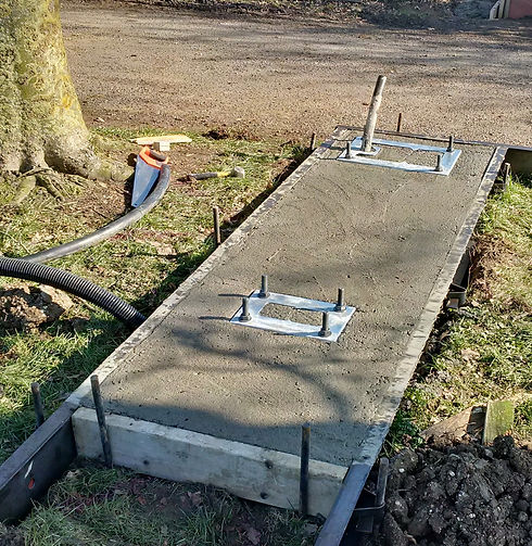
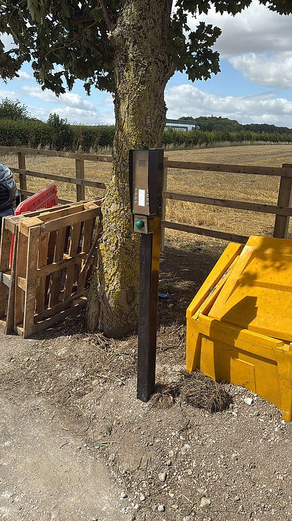
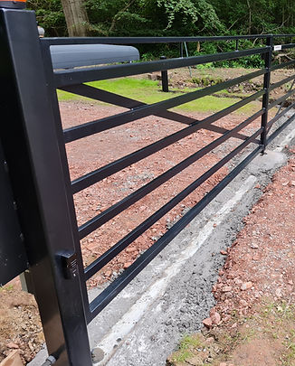
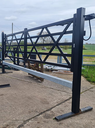
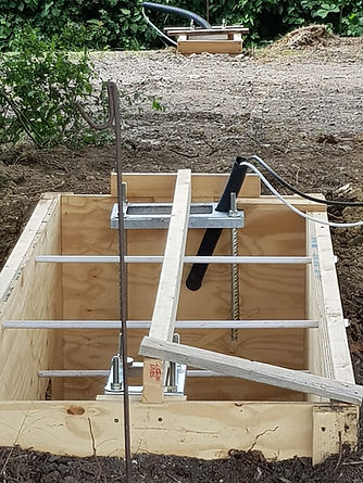
Installing a Cantilever Sliding Gate begins with precise groundwork to ensure safety and stability. A concrete foundation on the motor side measures approximately 1m wide, 2.5 to 4 m long, and 1m deep, with two templates and rebar bolts fixed before pouring. A second foundation on the latch post side, around 0.7m³, secures a third template with four bolts. Accessories require a duct with a draw cord across the opening, and 240V 6A single-phase power supply enters beneath the motor. Use string lines to align the gate centre line, ensure 100mm ground clearance, and maintain correct spacing from nearby fences to avoid entrapment.
We provide templates and assistance for those doing their own groundwork.
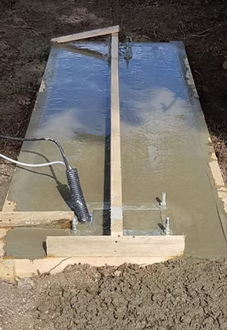
Note: the timber lining of these holes is not necessary. In this instance the base was put in a hollow. The timber shuttering was put in place then earth filled in around it.
A small timber edging around the top is all that is needed to give a tidy crisp edge to the foundation.
Sets the Standard for Secure Gate Installations
Trust Our Expert Groundwork Services To Lay The Perfect Foundation For Your Gate System. Call Today To Ensure Your Project Starts Strong And Finishes Right.